
Back to main site www.coloraid.de
A guide for LVT film recorder users
Warning: Use the information on this website on your own risk!
(some but not all stuff might be for advanced users)
On this website I try to publish information about the LVT / Rhino film recorders made by Kodak and Durst Dice usualy not found in the instruction manual. I hope it helps someone considering buying a used machine or those who are thinking about optimizing/fixing their recorder setup. Considering the small number of running machines left and my lack of time, please understand that the information below is far from complete nor well written. Skip reading parts you do not understand. But if you have problems understanding most things, get someone who does.as most items described will require some computer and darkroom knowledge. This page is not intended as easy guide for beginners without computer/darkroom knowledge. I will try to add more stuff to this site as time allows... so consider this guide work in progress from someone who's motherlanguage is not english. Also there is no fancy layout/design as I hardly think there will be more than 4-5 readers making use of this info. If you have specific questions not answered here, it's no problem to email me. But do not expect a detailed answer when I am busy otherwise....
After the first introduction of the LVT film recorder Kodak made a number of improvements to the machine. Most of the changes affect the reliablity, speed, size, useability and production cost of the machine. They usualy had little effect on the color quality of the output. Some older LVT machines support output with 3048 (120pix/mm) instead of 2048 dpi (80pix/mm) or output up to 16x10".
Since 2002 I have bought several machines (one new, four used) for myself and others. As I was never involved in the recorder business, the information provided here is simply based on what I have run into or the little I heard. I guess there are other people with far more knowledge on what type of LVT machines are out there. So take the information with care as it's likely incomplete or even wrong (infos are welcome).
Here my personal pro and cons of getting a certain model, starting with the latest model:
Only one of several recorders I bought used were working as described or had all the required parts to get going. While often missing parts can be easily origanized, you might want to check with the seller before buying. Maybe the seller simply has forgotten the parts:

The LVT instruction manual describes everything you need to know for installing and connecting the hardware. There are some things you might find usefull or should consider:

WARNING: Once you finished installing the recorder hard- and software, be aware that printing might still not be possible until you have setup the photomaterials.txt file correctly. A fresh installation of the LVT Windows software will install a default photomaterials.txt listing the available materials for the software wich likely does not match your recorders internal material setup. As noted above, try to get as much info from the previous owners material setup and if you are lucky you might be able to print... otherwise you need to check and setup the materials settings first. But more on this later in photomaterials section below.
If your machine doesn't work or the first print causes a fuse to blow, do not panic or do something stupid. Try to get as much details about what happened as possible (logging as described in the next section was on? What exactly happened and when? Did you smell something?...). Have a look at the hardware if there is something wrong or visible. Check out the section Errors and Repairs . And before you try something stupid that makes things worse, take a day off and/or maybe get help.
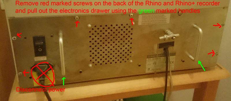
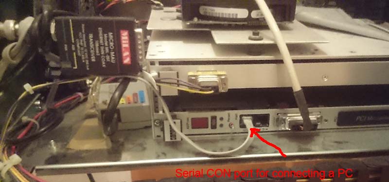
At least the recorders with a DEC AXP board (Rhino, older LVT with NT head?) do have DEC MMJ CON port beside the network AUI port that can be connected to a computer in order to display the recorders logging messages and also to enter the configuration menu that is usefull for changing the recorders IP address. I can't remember, but I guess there is also a serial port you can connect to on the 486 PC motherboard of the Rhino+ (most likely requires a null-modem serial cable for a PC connection). I have yet to see a Rhino with a serial port at the back of the case as described in the LVT instructional manual. Usualy there is just a whole in the back with the network/serial cable coming out (see the image below).
The messages logged from the recorders CON port are also often the only way to tell what exactly is keeping your recorder from working. So I strongly recommend to always have your recorders serial port connected. Note while this documentation is for the Rhino, other versions of the older LVT recorders with DEC AXP board usualy have a similar MMJ CON or serial port for logging. Just look for it or check below images.
You can find the MMJ jack on the DEC AXP board marked with CON. Usualy you need to get a MMJ- >DB9 female cable for connecting the recorder to typical PC DB9 serial port on a PC. In case you have no cable, check out ebay. Often you need to buy a DEC cable with MMJ plug on both ends and a MMJ to DB9 or DB25 adapter separatly. In order to find the CON port you need to open the recorders electronics drawer at the back of the Rhino:

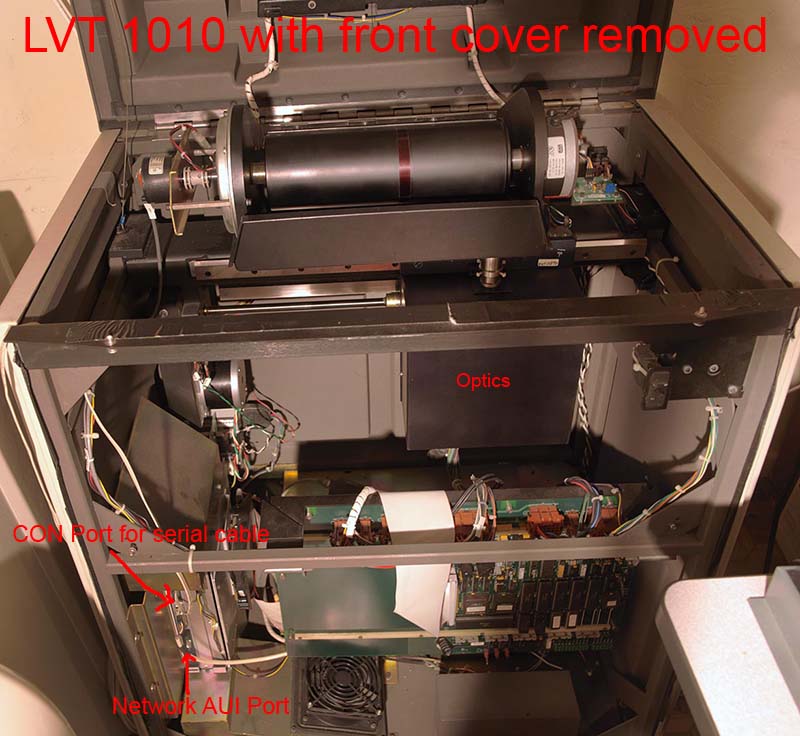
On the older/larger LVTs you find the CON port in the lower left front. In order
to access it you first need to remove the front cover:
Often there is no serial port available on the modern computers nor do you want another serial cable from the recorders dark room to the room with the PC. In order to avoid having that extra serial connection to your PC you can use a cheap terminal server (Moxa N5150A, Moxa N5110A, Lantronix MMS1,....) to connect the recorders serial port to your network in the dark room. Than you can simply connect to the recorders serial port via the existing network from your PC.
When connecting the recorder directly to a serial COM port on your PC you can also use the terminal software already shipped with Windows to display the recorder output. Note that the LVT software installs a "LVT Terminal" in the Windows start menu wich basicly calls the MS Windows terminal software and also provides a preset function key to enter systemlvt (read below). However, that terminal software has limited features and with terminal servers you definitly need TeraTerm or something similar able to connect via network instead of serial port or to allow simply starting the terminal software with logging on.
I usualy recommend to install the free TeraTerm 2.3 software in order to connect
to the recorder. But otherwise nearly any simply terminal software should do
fine.
WARNING: At least teraterm 4.65 doesn't really work here with the Rhino... so
2.3 is recommended.
WARNING: Putty as alternative to TeraTerm does cause a reboot of my Rhino recorder
when connecting. So would avoid Putty for now.
The serial connection parameters are usualy 9600 Baud, 8N1 and XOn/XOff handshake. If you use a terminal server as recommended you need to setup the terminal server and you need to specify a telnet server port that you use to connect to the terminal server from your PC (on Lantronix ETS/MMS servers this tends to by port 300x with x being the serial port number used on the terminal server. On Moxa N5150A and Moxa N5110A you can easily configure the port number).
After installing TeraTerm, you can use the Windows explorer in order to create a link to the executable ttermpro.exe on your Windows desktop. You can edit the arguments used by link to start TeraTerm. For instance in case of my terminal server found at 192.168.0.252:
C:\Programme\Modem\teraterm\ttermpro.exe telnet://192.168.0.252:3001
So basicly all I need to do is click on that desktop icon in order to get a TeraTerm window connected to the terminal server with the recorders serial port connected.
Please read the TeraTerm documentation on how to setup TeraTerm and for instance to automaticly start logging your sessions.
Testing the connection: If everything is connected/configured correctly, you should see messages reported by the Rhino during boot, printing or also when simply starting the LVTUIS software. If not, check all your serial port settings and also the wiring of the used cable.
An example of a complete log of a Rhino turning on/booting can be seen here.
Beside reading the logging messages reported by the recorder you can also enter a configuration menu by entering following command in the terminal software:
systemlvt
and than press return. The "Configuration Utility - Main Menu" should be dislayed allowing you for instance to change the IP address of the recorder.
Configuration Utility - Main Menu
The current printer model is 1010.
0 - Exit configuration utility
1 - Select the printer model
2 - Alter the network address
3 - Alter the fast scan offset
4 - Alter the slow scan offset
5 - Alter the print counter
6 - Alter the error reporting level
7 - Alter the reset timer value
The default IP address 150.102.200.150 of the recorder is usualy not matching your inhouse network subnet. While you can use a separate network card in your computer for the recorder, this is often not ideal. So here I describe on how to change the recorders IP address on a recorder with DEC AXP board so that you can simply connect it to an existing network. The IP address on the Rhino+ most likely can't be changed that easy as the Rhino+ boots from a floppy disk and connects to a FTP server. So you need to make changes at least to the data on the floppy disk wich is most likely some work.
Press 2 as indicated in the main menu noted above and you can change your recorders IP address:
2
Configuration Utility - Alter the Network Address
Current network address is 150.102.200.150.
Please enter the new network address [X to eXit]: 192.168.0.249
Configuration update in progress, please wait...
Note that after changing the recorders IP address you also need to configure
the Windows software to access that new address. This can be done by running
the regedit command in Windows. Search for PRINTER_1 wich
holds a NETWORK_INFO string with the ip address used by the software:
150.102.200.150 5001 50
Alter the ip address as wanted and after a reboot you should be able to output with your recorder.
While installing the recorder hard- and software is often quickly done, there is usualy the most work intensive part still left before you can make your first print. You need to setup software and recorder for the material you want to print. In the past you could basicly call the Kodak service and someone did this for you in a couple of hours. Or in case your recorder was new, it was already setup for a number of materials. I am afraid things are worse nowadays. Most recorders sold used seem to have a setup that likely is not working or optimal for your job. Also the available photomaterials have changed. A Velvia 100 slide film requires different adjustments than the Kodak EOF film. I hope I can fill some blank areas with this guide the LVT instruction manual doesn't cover and reduce the amount of work needed for setting up the recorder for a specific material. But basic color and darkroom knowledge and some time is required as the job is not always easy if you want an optimal output from your recorder. Please also read the LVT instruction manual first as understanding the information below requires knowledge from that manual.. So let's start with the various files and settings controlling the color and materials:
When installing the LVT windows software, the software will install a PhotoMaterials.txt file inside the config\Printer_1\Resources directory located in the LVTUIS program directory. The PhotoMaterials.txt file basicly lists the available photomaterials you can select and print using the LVT software. It's the first file you should check/edit:
8X10EOF_V1195~POS~6~RGB~TA~
4X5E100S_V1195~POS~6~RGB~TA~
8X10E100S_V1195~POS~6~RGB~TA~
4X5TMAX100_V790~INT~8~VIS~TA~
8X10TMAX100_V790~INT~8~VIS~TA~
4X5TMAX100_V1294~INT~8~VIS~TA~
8X10TMAX100_V1294~INT~8~VIS~TA~
4X5E64T_V1195~POS~5~RGB~TA~
8X10E64T_V1195~POS~5~RGB~TA~
4X5VPS_V196A~INT~9~RGB~TM~
8X10VPS_V196A~INT~9~RGB~TM~
4X5PRT_V197A~INT~7~RGB~TM~
8X10PRT_V197A~INT~7~RGB~TM~
Each line defines a photomaterial you can use in the LVT software. Several informations about a material are provided separated by a ~ character on each line. As far as I can understand it 8X10EOF_V1195~POS~6~RGB~TA~ defines following:
8X10EOF_V1195: name of the photomaterial. This
is also used as basename for AIM files, LUT files, DMP files and more used by
the software. Just check the files in the various directories under config\Printer_1
what filenames you need to use. For instance the AIM file for the material must
be named 8x10EOF_V1195cmyPOS.aim
POS: Means that the material requires an RGB LUT with normal
increasing output (ie. RGB image white becomes 4095 and black is 0 in the output)
6 This one is important. It selects the material setting saved
inside the recorder for the output. The material settings are described later
and they basicly provide some control over exposure time, filter used, aperture
size, available print resolutions.
RGB~TA these settings specify the densitometer measurements
needed when you measure a calibration strip.
You can edit the photomaterials.txt file to your liking.
That is, you can change the order, add or remove entries. But there is one thing
you must take care:
WARNING! The recorder software remembers the entry number of the last photomaterial
printed. When starting the LVTUIS software there must be a matching entry in
photomaterials.txt or else the software will not start. So you can't
simply add a material for tests at the end, do a test print and than remove
that last entry in the photomaterials.txt file as this will cause the software
not to start again. If this happens, simply add an entry again so that the software
finds an entry at the start and do a test print with another material before
removing the last entry again.
After adding a new entry to the photomaterial.txt file you also need to add a matching .aim file in the config\Printer_1\aims directory. Aim files are used during calibration of the recorder. They basicly define what output density the recorder should provide for a specific R, G or B image value. Similar to the PhotoMaterials.txt entries there is only a small number of aim files provided with the LVT software and most of the films are hardly available anymore. Check out the LVT instruction manual for more info about the available aim files and what dmin/dmax they require from your film processing. Creating a new aim file for an unsupported film requires some knowledge if you want to get good and reliable results from your recorder. So usualy you can't simply use the aim file for Kodak EOF with a Provia 100F slide film or the Kodak TMax aim file with an Ilford FP4+. Even if you got an aim file for your material from someone, you at least need to make sure that your film processing reaches the density range required by the aim file.
All photomaterials defined in the PhotoMaterials.txt file select a material setting saved inside the recorder. In the above entry 8X10EOF_V1195~POS~6~RGB~TA~ the material setting 6 is selected. The material settings can be accessed via the The monitor diagnostic menu . So when you got a used recorder and want to use 8X10EOF_V1195 you need to make sure that the recorders material 6 setting really is for Kodak EOF films and your E6 film processing is also working normaly. I am afraid most used recorders I have seen have been modified and material 6 rarely was still setup for Kodak EOF films.
So after photomaterials.txt and aim file, you should check what material setting are saved inside the recorder. Use the tabl command in the The monitor diagnostic menu. Than enter display followed by 6:
WELCOME TO MONITOR DIAGNOSTICS. ENTER "HELP"
FOR A LIST OF COMMANDS.
$tabl
ENTER "MODIFY" TO MODIFY A TABLE ENTRY,
"DISPLAY" TO DISPLAY A TABLE ENTRY,
OR "EXIT" TO RETURN TO MONITOR DIAGNOSTICS> display
ENTER MATERIAL # 0-19> 6
20,200,4,15
40,110,5,15
80,65,6,14
0,0,0,0
0,0,0,0
0,0,0,0
0,0,0,0
0,0,0,0
0,0,0,0
0,0,0,0
0
In order to understand the numbers, let's have a look at the line with 80,65,6,14 and describe the meaning:
80= Print resolution in lines/mm this setting was made for. Note that the number of lines printed and line width can be controlled separatly.
65= aperture size (basicly the width of the light beam exposed). So
print resolution (or should I say the number of lines exposed per mm) and line
width can be controlled separatly.
11= number of the filter used on the filterwheel (see Installing filters below).
15= drum speed (3-15 seems allowed). Basicly controls the exposure time.
Note that the material 6 setting above has multiple entries for different print resolutions. So when printing photomaterial 8X10EOF_V1195 the print resolutions the material 6 entries listed above allow are 20,40 and 80 pix/mm. You can not have multiple entries with identical print resolution in one material number.You will fail if you try to print resolution 60 lines/mm even if the LVTUIS software allows you to select that resolution simply because there is no working material setting for it.
It seems that on some recorders not all material numbers allow printing with all resolutions. Also some versions of the Rhino recorders had no aperture and only allowed printing with 80 pix/mm. So if you can't print and you are absolutly sure that all settings are correct, try saving your settings using a different material number. For prints 80 pix/mm at least material 5-9 seems to work on all recorders.
When you got a recorder without any information from the previous owner about the material setup, it's usualy best you simply measure the installed filters using your densitometer and also keep a record of all material settings saved inside the recorder. Each LVT recorder is slightly different and as a result one recorder setup might not work with another. However you can often (not always) use another recorders setup as orientation and make a guess about what material settings are good for you. For instance take the settings from the material sheet example as orientational reference.
As described in the LVT instructional manual, when calibrating the film recorder for a given aim file, the calculated calibration LUT should result in output values of 100-400 at the low end, and 1800-3500 in the high end. Based on experience with my own calibration software I would rather recommend 150-400 at the low and 2000-3200 in the high end as there are otherwise visible problems you can run into when using a too low/high output value. The .dmp files written by the LVTUIS software during a successfull calibration does list the output values. So the job of the material setting and filter installed is to ensure that the output values are within an optimal range and maximum print speed. This requires an optimal color filter that balances the three colors. An additional neutral filter if needed and small adjustments to the drum speed should get the LUT output values in the wanted range. The neutral filter choosen should result in a drum speed close to the maximum of 15 in order to keep printing time low. When getting a recorder it usualy takes 2-5 films in order to find a material setting and filter that works well. For a person without much experience and a recorder that requires changes to its material settings, this usualy means you might spend 2-3 days to setup the recorder the first time. It easily becomes a lot more if you have no idea what your doing or the used film processing is unstable/faulty. From my experience, half the pro E6 labs fail to provide a decent stable and correct film processing.
[ToDo: List filter/material setting differences between slide films....]
[ToDo: Finish Photomaterials section/info....]
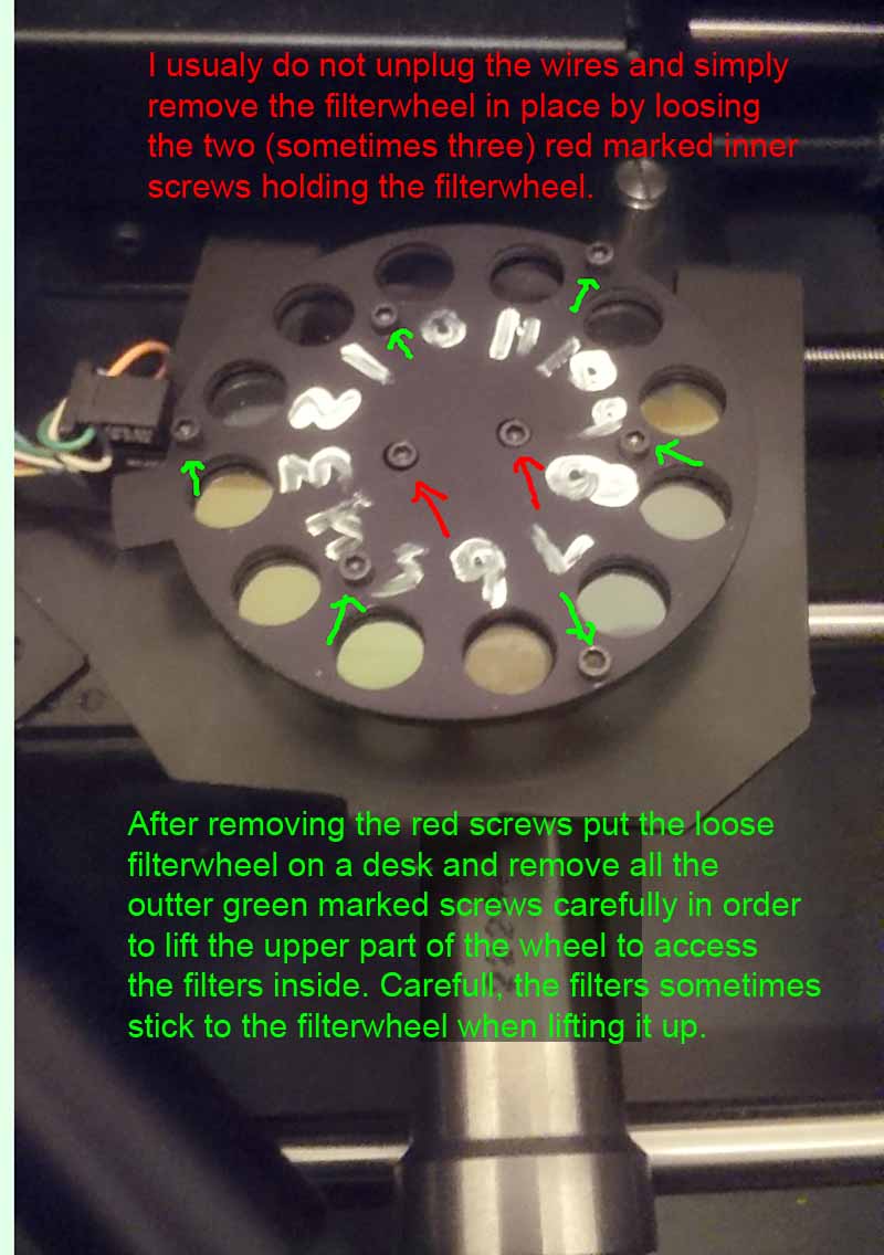
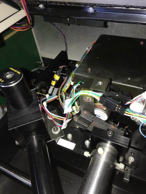
The recorder uses filters to balance the color channels and to roughly control the amount of light used to expose a material. Depending on the exposed material and print resolution you might need different filters and thus a filterwheel with several different filters is used. The filters only offer a rough adjustment of the output. Additional settings like drum speed (= exposure time) and an output LUT allow a more precisse control of the colors. The images below show you how to access the filters.
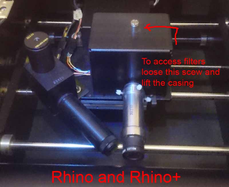
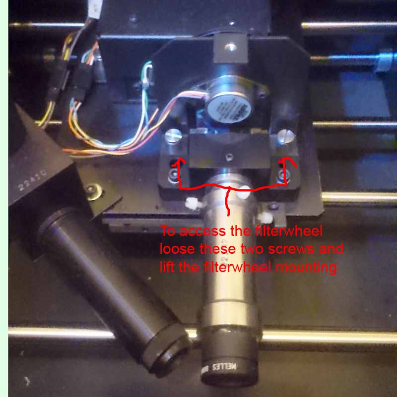
On the older larger LVT recorders things are only slightly different to the
Rhino/Rhino+. Here you need to remove the black optics casing below the drum.
Than you should be able to see the filterwheel incl. mounting as shown below.
As the access is not as easy as on the Rhino/Rhino+ it is required to disconnect
the cables for the filterwheel motor and sensor and remove the complete mounting.

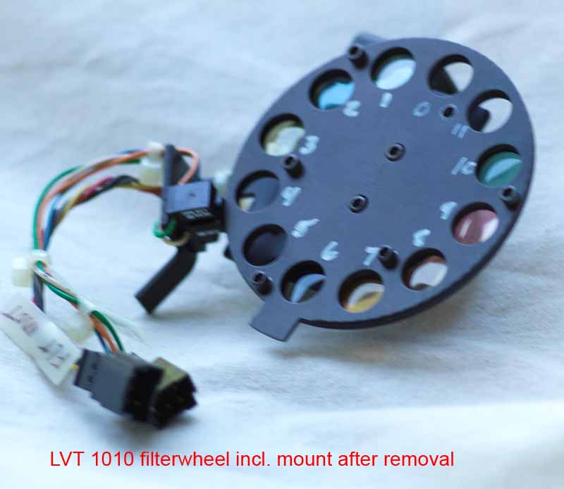
There were also other filterwheels used inside the recorders. So if your recorder differs from the above description, don't be surprised and adapt to it. Here are some images of other filterwheels found:
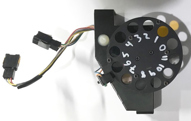
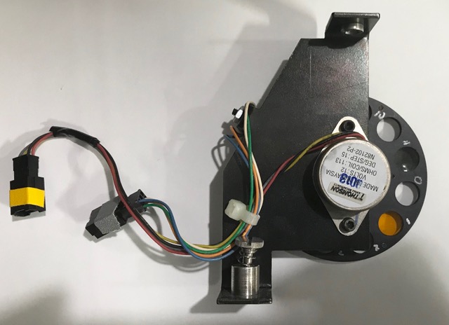
Note it seems common practice to not install any filter in position 0. This is for instance usefull for initial test with new materials.
Keep a record of all installed filters, their densities and what they are used for. For instance use something similar to the material sheet to keep record.
[ToDo: Add Content]
[ToDo: Add Content - Graphic of output processing steps]
The monitor diagnostic menu offers various hardware controls for diagnostic purpose but it also allows you to edit the important material settings used for the recording and selected by the photomaterials.txt settings. The menu is not documented in the LVT instruction manual despite being very important when setting up the machines for new materials and processing labs. This was often handled by a service technician called in the past. With basicly no technician left it is up to you to setup the material parameters using this menu. Please be carefull when using the commands of this menu. Some commands risk damaging your recorder if you do something nasty. With this menu you can basicly edit things like exposure time (drum speed) and more used with a specified material. The menu is not available on the very old DEC Vax based LVT recorders as here material settings are controlled by the VMS LVT software.
In order to access the menu you need to telnet into the recorder ip address. While there are many tools with telnet support (Putty, TeraTerm,...), but when in doubt I recommend to stick to the telnet tool shipped with Windows as this has always worked for me while I had problems with Putty. Note that on Windows XP computers the telnet tool is not installed by default and you need to install it from your Windows XP CDROM. Telnet is installed via the Start (button) -> Control Panel -> Add / Remove Programs-> (Click on Turn Windows features on and Off ) and than enable the "Telnet Client".
For connecting to the recorder using telnet open a windows console and enter folling command with the printers ip address:
telnet 150.102.200.150
After a successfull telnet connection is established there is no more prompt and nor echo from entering characters. Type in blindly the uppercase character M and a welcome message should immeaditly appear:
M
WELCOME TO MONITOR DIAGNOSTICS. ENTER "HELP" FOR A LIST OF COMMANDS.
Now you can follow the advise and enter help:
$help
FOLLOWING IS A BRIEF DESCRIPTION OF AVAILABLE COMMANDS. TO EXECUTE
A COMMAND, TYPE THE COMMAND AT THE $ PROMPT AND HIT RETURN.
ADCO MEASURES VARIOUS ANALOG VOLTAGES AND REPORTS THEM.
CLOC MEASURES VARIOUS CLOCK FREQUENCIES AND REPORTS THEM.
DACS DRIVES THE OPTICAL CHANNELS WITH 3 DIFFERENT FUNCTIONS.
DRUM,SP=X SPIN THE DRUM AT X RPS. THE ACTUAL SPEED IS REPORTED.
EMON EXITS MONITOR DIAGNOSTICS AND RESETS THE FILM RECORDER.
FLHM HOMES THE FILTER WHEEL.
FLRN,X MOVES THE FILTER WHEEL X NUMBER OF MOTOR STEPS.
FSET,X MOVES THE FILTER WHEEL TO FILTER POSITION X.
HELP OUTPUTS THIS HELP SCREEN.
OPHM HOMES THE OPTICAL HEAD.
OPRN,LE,ST=X MOVES THE OPTICAL HEAD LEFT X NUMBER OF MICROSTEPS.
OPRN,RI,ST=X MOVES THE OPTICAL HEAD RIGHT X NUMBER OF MICROSTEPS.
PRIN REPORTS THE # OF PRINTS DONE OR ZEROES THE PRINT COUNTER.
TABL GIVES ACCESS TO THE ON BOARD PRINTER LOOK-UP-TABLE.
TIME REPORTS THE # OF PRINT HOURS OR ZEROES THE PRINT TIMER.
Some usefull commands:
In normal operation the most usefull command is tabl as it allows editing the material settings.
[ToDo: Add Content]
As described in the LVT instruction manual you basicly use the
calibration software shipped with the LVT to fine adjust the color output. The
LVT calibration software generates a LUT file wich translates the 8 Bit/channel
image data to 12Bit/channel output values of the recorder. For calculating the
LUT the software needs an aim file describing what output density should be
printed for a given R,G or B image value and you need to print+measure a 26
step wedge. For this to work correctly, it is important that the LVT material
setup and filters used allready do provide a decently correct output. If the
material setup is rather wrong the LUT generated by the calibration software
will not be able to compensate this fault. Also if the filters installed do
not balance the R, G, B output decently, you might end up with Red being exposed
correctly but lack exposure in the blues the LUT can not compensate. So a good
material/filter setup is important for the calibration to work nicely as the
calibration only offers limited but very accurate control over the output.
When measuring the calibration wedge using an X-Rite densitometer I strongly
recommend to warm up the densitometer by doing >10 measurements right before
you start measuring the wedge. If you don't the X-Rite device will warm up during
your measurement and might shift a small amount. As the human vision is very
sensitive for certain faults in the gray axis there is little room for faults
if you for instance want to output neutral grayscales.
Before you perform a calibration always make a backup of your config\Printer_1
directory in the LVTUIS program directory. If something does not work
well during calibration you can easily restore the backup and make another attempt.
It actually makes sense to keep the backups from several last calibrations as
they allow you to detect changes and problems over time.
After each sucessfull calibration there will be a new .dmp file in config\Printer_1\dumps
providing you important information about how the calibration went. The .dmp
file is a textfile you can open in Notepad or a texteditor of your liking. It
does list the used aim values, densities measured for the wedge, old and new
output LUT values. Here you should always check if the newly generated LUT is
not reaching bad values like 0 or 4095.
The LVT calibration software uses an interpolation and not an approximation
function on the measured calibration wedge data. This means, any small fault
or noise in the measurement data will be fully reflected by the calculated LUT
output function. So try to make sure your measurement are correct for instance
by checking the .dmp file after calibration. Not a single measurement should
be faulty or off.
The LVT calibration software hates to extrapolate. If your aim file wants a density outside of the measured calibration wedge the generated LUT might not work well and at least another calibration update might be needed. This can be a rather serious problems in practice especialy if your film processing is not stable near DMin/Dmax. So a good and stable processing is important and if you can't improve the processing it might be better to change the aim fail to not get to close to the DMin/DMax recorder output possible with your processing.
[ToDo: Add Content]
The LUT files in the config\Printer_1\CalLuts subdirectory of the LVTUIS program directory are generated by the calibration software shipped with the recorder. The LUT files basicly fineadjust the color output of the recoder for a specific photomaterial and print resolution. Before I developed my own calibration software for the recorder I sometimes run into the problem requiring manualy editing the LUT wich lead to the quick&dirty development of two small console based tools (lut2dmp and dmp2lut). During the development of my calibration software I found it would be nice to have a nice graphic of the LUT and thus generated an Excel sheet that can be used together with the tools in order to get a nice image of the LUT::

The Excel sheet does not only graphicly show the LUT values. Identical LUT values reducing the number of shades printing per chanel are also visibly marked red. In the above Excel screenshot you see many red marked identical LUT entries because the exposure is still too strong resulting in rather low (<1600) output LUT values as indicated by the graphic. As noted in the photomaterials chapter above, the output values should at least reach 1800. I found that 2400 is more likely needed with slide films even with an optimal filter installed to avoid most/all identical LUT entries.
The tools, Excel sheet and a short readme file as manual can be downloaded from here . Sorry: These are simple console based tools without any easy to use graphical frontend. So you need to use the Command Prompt in Windows. I simply didn't want to waste time on a GUI. Tools are provided here despite I think they are unlikely used by anyone. For those unable but wanting to use the tools, the .dmp textfiles generated by the LVT software during calibration also lists all values of a LUT file and you might be able to use them. Note that the file format used for LUTs does not differ for negatives or positives, color or grayscale. So you can use the software with negative film LUTs despite the example/documentation notes only .pos LUTs for slide films.
[ToDo: Add Content]
[ToDo: Add Kodak E100G AIM and ICC profile]
[ToDo: Add FUJIFILM Provia 100F AIM and ICC profile]
[ToDo: Add FUJIFILM Velvia 50 AIM and ICC profile]
[ToDo: Add FUJIFILM Velvia 100AIM and ICC profile]
Over the time I run into several minor problems with the recorder. Often the only way to get more info on the cause of the problem is logging the terminal output of the recorder (see Using the Serial Consoleand Configuration Menu). So I strongly recommend to connect the terminal output in order to log it, even if there is no problem. I once was only able to identify/fix the problem because the logging was on when the problem appeared. Do not panic or do something stupid. Try to get as much details about what happened as possible. What exactly happened and when? Did you smell something (hopefully just a blown fuse)? Have a look at the hardware if there is something wrong or visible? And before you try something stupid that makes things worse, take a rest.and maybe get help.


Thanks goes to TC Reiner for providing the LVT 1010 images and Ian Mazursky for technical info and more images.
| Back to www.coloraid.de | Contact: wfaust@coloraid.de:
|
Last Edited: 23-October-2023 |